Netmapr Quick Start Tutorial
This document provides a simple tutorial, stepping through the basics of using netmapr. It guides
the reader through the creation of a simple network diagram from scratch using the various functions available
in netmapr. It assumes that you have already successfully compiled and installed netmapr.
The Basics
First things first - start netmapr, either by running /usr/local/bin/netmapr (unix) or double clicking
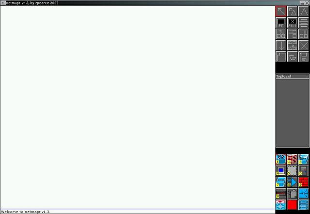
netmapr.exe (windows). You should see a screen similar to the following:
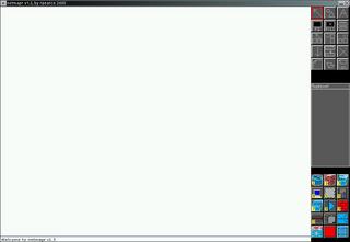
The various components of the screen you will use are:
Map Area: The large white area taking up the majority of the screen. This is where you will create your network diagram.
Toolbox: The set of buttons at the top right of the screen. Left (or in some cases, right) clicking the buttons here will change through different editting modes. At the moment, the "object selection" tool (a diagonal arrow) should be selected, indicated by a red box.
Objectbox: The area at the bottom right of the screen containing pictures of various network elements. Left clicking an object here will select the type of object to next add to your diagram. You will notice numbers underneath some of these objects - these indicate the shortcut keys which you can use to quickly select the relevant objects.
Map List: The grey box between the Toolbox and the Objectbox. This area lists all the sub-maps of the current map (this will be explained later).
Now we will create a very basic diagram perhaps representing a typical home network with a single computer, a
firewall, and an internet connection.
Add a firewall object
- Select the firewall object type by either clicking on the picture of the firewall in the Objectbox, or pressing the '2' key.
- Select "Add object" mode by clicking the second button in the Toolbox (with the picture of a triangle and a square) or pressing the 'a' key.
- Position the mouse somewhere around the middle of the Map Area and click the left mouse button. A firewall will appear underneath the mouse.
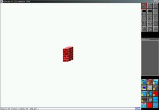
- Since the firewall is currently tiny, we need to resize it. Click and hold the right mouse button over the firewall you just created, and drag the mouse down and to the right to enlarge it. Let go of the mouse button when you are happy with the size
Your screen should now look similar to the following:
Add a network cloud
- Select the "network cloud" object type by either clicking on the picture of the cloud in the Objectbox, or pressing the '5' key.
- Select "Add object" mode by clicking the second button in the Toolbox (with the picture of a triangle and a square) or pressing the 'a' key.
- Place the cloud at the top right of the Map Area using the same method as you did for the firewall.
- Enlarge the cloud as you did with the firewall.
Add a PC
- Select the "PC" object type by either clicking on the picture of the computer in the the Objectbox, or pressing the '4' key.
- Enter "Add object" mode.
- Place the PC at the bottom left of the Map Area.
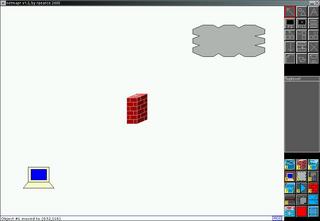
- Enlarge the PC.
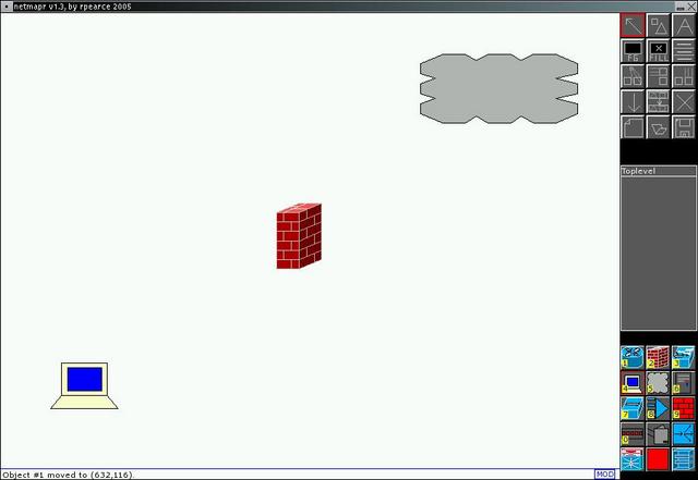
Your screen should now look similar to this:
Connect the objects
- First we will connect the PC to the firewall. Hold down the CTRL key, and use the left mouse button to drag a line from the PC to the firewall. A link will appear connecting the two. If you have a three button mouse, you can use the middle button instead of holding down the CTRL key.
- Now repeat the process to connect the firewall to the network cloud.
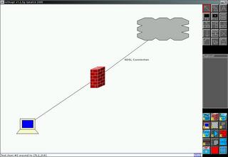
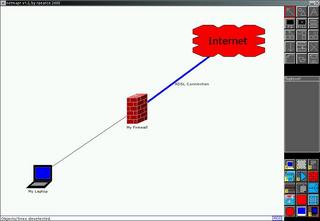
Your screen should now look similar to this:

You have now created a simple network diagram! At the moment it looks very basic - the next part of the tutorial will show you how to make the diagram more meaningful by adding text.
Adding Text
This part of the tutorial assumes that you have already completed the first section ("The Basics"). If not, please quickly run through it now as this section will build on the diagram you create there. We will now add some text to the diagram to make
it more useful.
Add text to Internet link
First of all we will add some text describing the Internet link.
- Enter "Text Entry" mode by either clicking the button with the image of the letter A on the Toolbox, or pressing the 't' key.
- Click somewhere on the white part of the Map Area (ie. not on one of the objects you have already created). A blue text cursor will appear.
- Type the words "ADSL Connection" then press ENTER.
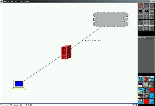
- Finally, left-drag the newly-created text over to the middle of the link between the firewall and the network cloud.
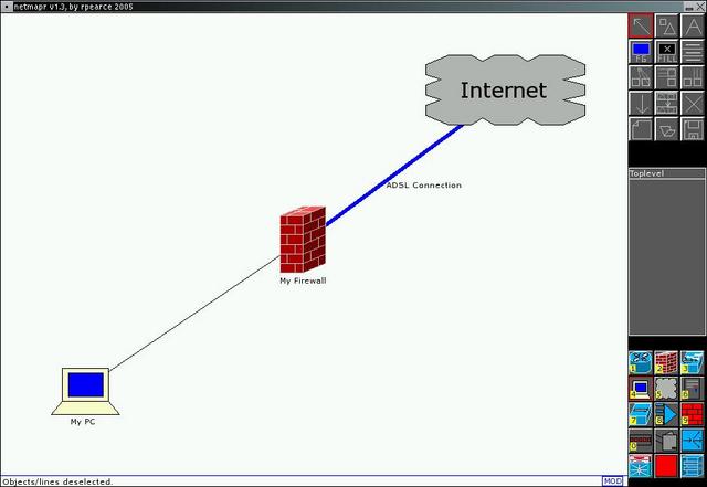
Your screen should now look similar to this:
Add descriptions to the PC and firewall
Rather than adding generic text to the map, you can also add text directly attached to an object. This way when you move
the object, the text will remain next to it.
- Enter "Text Entry" mode by either clicking the button with the image of the letter A on the Toolbox, or pressing the 't' key.
- Click on the PC at the bottom right of the Map Area. A blue cursor will appear underneath the PC.
- Type the words "My PC" then press ENTER.
- Left-drag the newly-created text so that it is directly under the PC object.
- Single click the newly-created text to select it. Notice that the PC is now highlighted in green, indicating that the text is attached to it.
- De-select the text by clicking anywhere on the background of the Map Area.
-
- Enter "Text Entry" mode again, and add the text "My Firewall" to the firewall.
-
Add description to Network Cloud
- Enter "Text Entry" mode again.
- Add the text "Internet" to the network cloud at the top right of your diagram.
- Left drag the text to the centre of the cloud.
- This text curretly looks a little small next to the huge cloud, so click and drag it with the right mouse button to make it large until it fits nicely within the cloud.
- Left-drag the newly-created text so that it is directly under the PC object.
- Single click the newly-created text to select it. Notice that the PC is now highlighted in green, indicating that the text is attached to it.
- De-select the text by clicking anywhere on the background of the Map Area.
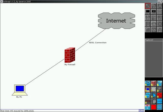
- Enter "Text Entry" mode again, and add the text "My Firewall" to the firewall.
Your screen should now look like this:
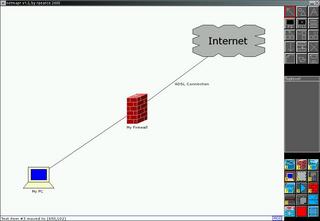
The full diagram is now starting to take shape. The next section will concentrate on those small details which make
the diagram more user-friendly and aesthetically pleasing.
Adding Details
This part of the tutorial will show you how to make your diagram look better by adding details such as colour. Again, it assumes that you have already completed the previous parts of the tutorial.
Colours and Styles
As an internet link is a different type of connection to that between the PC and the firewall, we should make it stand out. Perform the following steps:
- Left click once on the link between the firewall and the Internet cloud. Black squares will appear on its endpoints to show that it is selected.
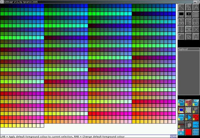
- Right click on the "FG" button in the Toolbox. The screen will change to show a colour palette like the following:
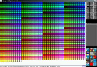
- Click on one of the blue squares. The map area will reappear, and the FG button in the Toolbox will now show the colour you have selected. The Internet link line will also now have changed colour to blue
- Left click anywhere on the Map Area backgroudn to de-select the link.
- Right click the "FG" button again, and select the colour black.
- Now we will make the Internet link a little thicker so that it stands out. Select the link between the firewall and the Internet again as you did above.
- You should see a "Line Type" button in the toolbox - it is actually subdivided up into three thin buttons, each with a single white line on it. From top to bottom the buttons control the thickness, style (solid, dotted, etc.) and arrowheads of a line. For now, we will just use the thickness feature. Right click the top sub-button three times. Each time you will see the Internet link increase in size.
- Click on the background of the map to de-select the Internet link.
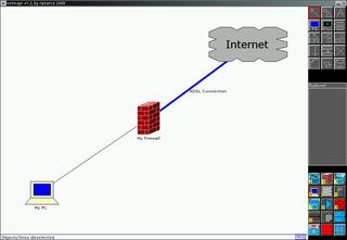
- Right click the "Line Thickness" button a further two times to return the curren line style to normal. Your screen should now look like this:
- Finally, let's make the Internet cloud stand out a little. Single click the cloud to select it, the right click the "FILL" button on the Toolbox. A colour palette will appear again.
- Select the colour red. The map area will return and the Internet cloud will now have changed colour. The FILL button will also show that you have changed the default fill colour.
- De-select the Internet cloud and right click the FILL button again.
- This time instead of clicking on a colour, left click anywhere over the Toolbox. This will turn off fill mode and the FILL button will now have a cross through it to indicate that new objects will not be filled.
Modifying Objects
Let's say that you just decided to sell your PC and replace it with a laptop. You could simply delete your PC object (by selecting it and pressing the 'DEL' key) and re-add a new object, but this would mean re-creating the attached text and re-drawing the link between it and the firewall. Instead, netmapr will let you simply change the object's type.
- Left click once on the PC object to select it.
- Either right click on the "Create Object" button in the Toolbox, or press the 'm' key (for "Modify).
- Currently the object box isn't showing the laptop object, so use the ',' and '.' keys to scroll the Object Box up and down until you can see the laptop object. If you have a wheen on your mouse, you can also simply position the mouse over the Object Box then scroll up and down using the wheel.
- Click on the laptop object in the Object Box. Your PC will now change into a laptop.
- Select the text beneath the PC and press the F2 key (or just double click the text) to edit it, and change it to read "My Laptop".
- Rather than always scroll around to select objects, you might want to assign a shortcut to quickly select one. Position the mouse cursor over the Laptop icon in the toolbox and press the '9' key. A small '9' will appear over the laptop icon, indivating that any time you press the '9' key this object will now be selected. The same goes for all the number keys on your keyboard ('0' through '9').
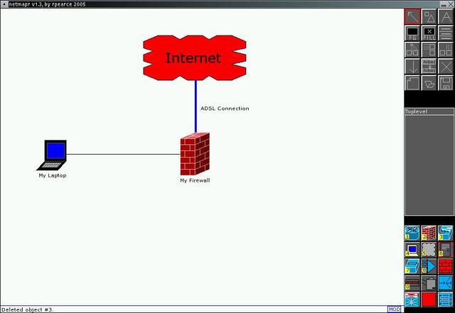
Your screen should now look like this:
Aligning Objects Using Snap-To-Grid mode
Diagrams generally look more professional when all the objects are nicly lined up. Rather than make tiny adjustments by
hand so that all the links between objects are completely straight, netmapr provides two ways to make this easier. The
first is snap-to-grid mode, and the second is via the automatic alignment tools.
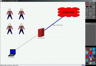
- First we will explore grid more. Press the 'g' key and a grid will appear over your diagram.
- Select a new object type from the Object Box (any one will do), and add it to your diagram.
- Now try left dragging the object to move it around - you will notice that it always "snaps" to the nearest grid location. This makes it much easier and faster to line up objects. Try adding some more objects to the diagram and notice how easy it now is to align them:
Aligning Objects Using Automatic Alignment
As fast as grid mode is, netmapr provides an even fast way of doing this! The third row down in the Toolbox consists of (from left to right) the Match Size tool, the Align X tool and the Align Y tool.
- For each of the objects you craeted in the last section, click the object once then press the 'DEL' key to remove it.
- Press the 'g' key again to disable snap-to-grid mode.
- Select your Laptop object, then either select the "Match Y" tool from the Toolbox (image of a box moving down to meet another box) or press the 'y' key.
- Left click once on your Firewall object. The Laptop will automaticall move upwards so that it is exactly lined up with the firewall! Notice that the "My Laptop" text remains attached to the Laptop object.
- Now we will align the Internet cloud. Select the Cloud, then click on the "Match X" button (box moving right to meet another box) or press the 'x' key.
- Left click once on your Firewall object. The Network cloud will move sideways to end up directly above the firewall. Note that in this case the "ADSL Connection" text will remain where it is, as it was not attached to any object. Manually move this text back next to the link by left-dragging it.
- The last auto-alignment tool is the "Match Size" tool. Select the Laptop object again, then click on the "Match Size" button (directly to the left of the "Match X" button) or press the 'b' key.
- Left click on the Firewall object. The Laptop will now change size to match that of the firewall. This will probably look a little silly though, so use the right mouse button to resize the laptop back to normal.
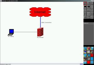
Your screen should now look like this:
Drilling Down
This final section deals with multi-tiered network maps. These are commonly used in complex network diagrams where it is neccessary to summarise parts of the network (generally into a cloud object, but any type can be used). Netmapr then allows you to "drill down" into the cloud to obtain more details about that part of the network.
Creating a New Sub-map
- First we will create a summary cloud - add a new Network Cloud object to the map, to the right of your Firewall object and link it to the Firewall. Add the text "Office Network" to this cloud.
- Now single click on the newly-created cloud, and click on the "Drill Down" button in the Toolbox (an arrow pointing downwards) or press the 'd' key. A prompt will appear asking you for the name of the new map.
-
- Leave the name as the default of "Map #1" for now and press ENTER. Your network diagram will vanish, leaving a blank map area! Notice that the name at the top of the Map List has now changed from "Toplevel" to "Map #1" and that the "go back" arrow had appeared directly under it. This shows that you are now editting a new sub-map.
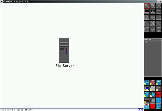
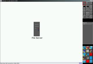
- Add a Server object to this map (shortcut key '6') and add the text "File Server" to it.
Your screen should end up looking like this:
Map Navigation and Renaming
- Now that you have created a new map, it is useful to name it. Click the text "Map #1" at the top of the Map List and a prompt will apear asking you to change the name. Change it to "Office Network".
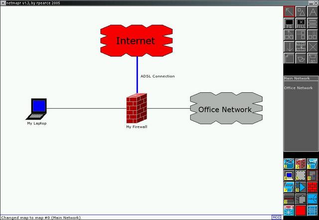
- At the moment we have drilled down into the "Office Network" cloud. To go back up, click on the arrow in the Map List (the "go back" arrow - just under the map title) or press the 'BACKSPACE' key. You will now find yourself back at your main network diagram. Notice that the Map List now shows the sub-map "Office Network" which you just created:

- Rename this main map from the default of "Toplevel" to "Main Network".
- Now that we have creaed and named two maps, we can easily move between them. There are two ways to do this - the first way is via the Map List. Click on the text "Office Network" in the Map List at the very right of the screen. Your view will change to the sub-map.
- Click on the "go back" arrow or press the 'BACKSPACE' key to go back to the Main Network map.
- The second way to traverse into submaps is to double click on the appropriate object. Double click on the "Office Network" cloud object this time instead of the entry in the Map List - you will end up back in the sub-map view.
- Go back to the Main Network map again.
- The final map navigation feature provided by netmapr is the ability to create a "link" from an object to an existing map. Select the Internet cloud (make sure you select the cloud and not the text), then click on the "Create Link" button (directly to the right of the "Drill Down" button). A prompt will appear asking you which map to link to, as following:
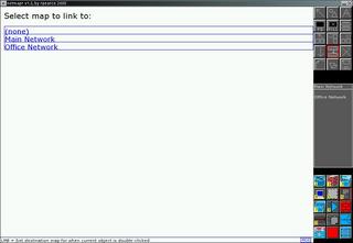
- Click on the blue "Office Network" box to create the link. The Main Network map will re-appear.
- Now double-click on the Internet cloud - you will end up in the sub-map! To undo this, you can select the Internet cloud again, click the "Create Link" button, then select the "(none)" option.
- Finally, if you want to save this map to experiment with later, simply click on the "Save" button (a picture of a floppy disk) or press the 's' key, then enter a filename.
Summary
This concludes the netmapr tutorial - if you would like to further explore the features provided, a demo map named 'example.map' should have been provided with your netmapr distribution. This shows off the various features of netmapr and can be used to
see the kind of things which are possible. If you would like any further help, or have any feedback then feel free to
contact me at rob@nethack dot net!